Views: 0 Author: Site Editor Publish Time: 2026-09-29 Origin: Site


Uneven web formation reduces product strength, increases waste, and causes downstream defects. In high-speed carding systems, these issues often result from mechanical wear, airflow changes, drive synchronization problems, or raw material variations.
A systematic troubleshooting approach helps identify the true cause by checking machine components, airflow balance, and control accuracy. This enables targeted repairs, better maintenance planning, and stable web quality.
Mechanical Wear is the Leading Culprit: Degradation of metallic wire on the cylinder, doffer, or flats accounts for the majority of localized web defects and nep generation.
Precision Gauging is Non-Negotiable: Variations as small as 0.001 inches in cylinder-to-doffer settings can trigger significant web weight irregularities (CV% spikes).
Aerodynamics Dictate Fiber Transfer: Unbalanced airflow or compromised suction systems disrupt the delicate fiber transfer process, leading to cloudy or patchy web structures.
Drive Synchronization is Critical: Micro-slippage in belts or lag in servo drives can cause drafting variations that mimic mechanical faults.
Upstream Feed Uniformity is Prerequisite: Diagnostic efforts at the carding stage will fail if chute feed variations, opening room faults, or improper fiber finishes are not first eliminated.
Table of Contents
Establishing strict baseline metrics is the first step in diagnosing web quality issues. The Coefficient of Variation (CV%) serves as the primary indicator of web weight consistency. A sudden spike in short-term or long-term CV% points directly to mechanical or drafting anomalies. Beyond weight variation, nep count per gram provides insight into fiber parallelization and wire condition. Visual uniformity standards also play a role. Operators must monitor for cloudiness, longitudinal stripes, and transverse bars on the web board. Setting definitive thresholds for these metrics allows maintenance teams to distinguish between normal operational variance and actionable mechanical faults. For instance, a CV% exceeding 5% in a standard polyester nonwoven application warrants immediate mechanical inspection.
Ignoring minor web irregularities compounds errors throughout subsequent manufacturing stages. In spinning applications, uneven webs cause drafting breaks, increase yarn hairiness, and lead to inconsistent dye uptake in the finished garment. In nonwoven production, web weight variations translate directly into weak spots during hydroentanglement or needle-punching. These weak spots compromise the fabric's barrier properties and tensile strength. The financial impact includes increased scrap rates, downgraded product classifications, and accelerated wear on downstream machinery forced to process irregular material. Running a machine with known web defects rapidly consumes profit margins through wasted raw fiber and lost machine hours.
Before initiating any mechanical troubleshooting, you must stabilize the operating environment. Temperature and relative humidity directly influence fiber friction and static electricity generation. Maintain strict environmental controls to rule out climate-induced drafting issues. A standard operating environment for cotton processing typically requires 55-65% relative humidity at 75°F. Furthermore, safety protocols are non-negotiable. Implement rigorous Lockout/Tagout (LOTO) procedures during all static mechanical checks.
Isolate the main power disconnect and apply a standardized padlock.
Bleed off all compressed air from the pneumatic tensioning systems.
Wait a minimum of three minutes for the main cylinder to stop coasting completely.
Verify a zero-energy state using a calibrated multimeter on the drive terminals before opening any access panels.
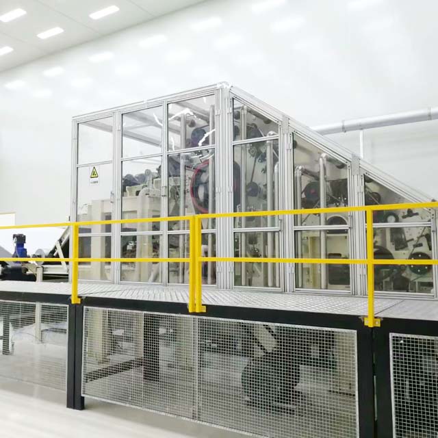
The condition of the metallic clothing on the cylinder, licker-in, and doffer dictates the efficiency of fiber opening and transfer. Worn, damaged, or loaded wire fails to grip and release fibers consistently. When cylinder wire loses its edge, it struggles to parallelize fibers against the flats, generating neps and thick places. Damaged licker-in wire causes poor initial tuft opening, feeding irregular clumps into the main carding zone. Additionally, dull flat tops fail to extract short fibers and trash effectively. This mechanical degradation ranks among the most frequent uneven carded web causes, resulting in poor fiber separation and localized web defects. Inspect the wire closely for hooking, bruising, or missing teeth, particularly on the edges where fiber tends to roll.
Carding relies on microscopic clearances between rapidly moving surfaces. Variations as minor as 0.001 inches in the cylinder-to-doffer gauge disrupt the transfer of fibers. Eccentric cylinders or doffers—where the roller is no longer perfectly round—create cyclical variations in the web, commonly known as drafting waves. Incorrect settings between the feed plate and licker-in alter the intensity of the initial fiber draft, leading to tuft plucking rather than smooth combing. Similarly, improper clearances between the cylinder and flats reduce carding intensity, allowing unseparated fiber bundles to pass through and disrupt web uniformity.
Component Interface | Standard Clearance Range (inches) | Symptom of Improper Gauge |
|---|---|---|
Feed Plate to Licker-in | 0.010 - 0.015 | Plucked tufts, fiber damage, irregular feed. |
Licker-in to Cylinder | 0.007 - 0.010 | Poor tuft transfer, excessive fiber drop-out. |
Cylinder to Flats | 0.008 - 0.012 | High nep count, uncarded clumps, poor parallelization. |
Cylinder to Doffer | 0.004 - 0.006 | Web cloudiness, severe fiber recycling on cylinder. |
Fiber transfer within a high-speed card relies heavily on controlled air currents. The boundary layer of air surrounding the cylinder must be precisely managed. Blocked suction points, damaged undercasings, or incorrect fan speeds disrupt this aerodynamic balance. When airflow is compromised, fibers may detach prematurely or fail to transfer to the doffer. This leads to fiber recycling, where fibers travel multiple times around the cylinder. Recycled fibers become over-carded, damaged, and eventually clump together, creating a cloudy or patchy appearance in the final web. Inspect all undercasing segments for burrs, lint buildup, or misalignment that could trip the boundary layer.
Drafting consistency requires absolute speed synchronization between rollers. Worn drive belts, slipping pulleys, or failing Variable Frequency Drives (VFDs) introduce micro-variations in roller speeds. If the doffer speed fluctuates even slightly while the cylinder remains constant, the draft ratio changes instantly, causing transverse bars in the web. Asynchronous speeds between the feed roller and licker-in cause irregular tuft feeding, impacting short-term web evenness. Identifying these power transmission failures requires precise rotational speed monitoring using strobe tachometers under actual load conditions.
Diagnostic efforts at the carding stage often uncover upstream process failures. Irregular batt weight delivered from the chute feed system forces the card to process varying volumes of fiber, overwhelming the autoleveller's correction capabilities. Variations in fiber staple length, crimp, or spin finish levels also manifest as unevenness. When processing synthetic fibers like polyester or viscose, static electricity buildup causes fibers to repel each other or cling to metallic surfaces, disrupting web cohesion. Conversely, natural fibers like cotton may introduce varying trash levels that load the wire and interfere with carding efficiency.
The final stage of web formation is highly sensitive to tension variations. Improper tension between the doffer, stripping roll, and crush rolls causes the fragile web to sag or stretch. Excessive tension drafts the web unevenly, creating thin spots or longitudinal tears. In nonwoven applications, worn delivery aprons or misaligned crosslapper entry points distort the web immediately after it exits the card. Maintaining precise speed ratios in the take-off zone preserves the uniformity achieved in the main carding zone. Operators must routinely check the surface condition of the stripping rolls for grooving or wear.
Effective troubleshooting begins with accurate defect identification. Manual inspection using web boards provides immediate visual feedback on neps, trash, and gross irregularities. However, automated, inline optical scanning systems offer continuous, objective data. These sensors detect microscopic variations in web density and map specific visual defects to their mechanical origins. By analyzing the frequency and pattern of cloudiness, longitudinal stripes, or transverse bars, technicians can isolate the failing component without unnecessary machine teardowns. Relying solely on the naked eye at production speeds of 150 meters per minute is insufficient for modern quality control.
Utilizing a structured matrix accelerates the diagnostic process by linking specific web defects to their most probable mechanical or aerodynamic origins.
Web Defect Pattern | Primary Mechanical Origin | Secondary Aerodynamic/Drive Origin | Recommended Diagnostic Action |
|---|---|---|---|
Longitudinal Stripes | Localized wire damage on cylinder/doffer; blocked flats. | Damaged undercasing disrupting airflow. | Inspect wire for bruising; check undercasing alignment. |
Transverse Bars (Periodic) | Eccentric rollers; worn bearings; damaged gears. | Slipping drive belts; VFD speed oscillation. | Perform vibration analysis; check belt tension and motor load. |
Cloudy or Patchy Web | Dull cylinder wire; improper cylinder-to-doffer gauge. | Aerodynamic imbalance; blocked suction points. | Measure dynamic gauge; map static pressure in suction zones. |
High Nep Count | Worn licker-in wire; improper flat settings. | Fiber recycling due to poor doffer transfer. | Inspect wire sharpness; verify flat-to-cylinder clearances. |
Mechanical degradation often presents as abnormal vibration before it causes severe web faults. Deploying vibration sensors helps detect bearing wear, cylinder imbalance, or eccentric rollers early. A comprehensive mechanical audit must include dynamic gauge measurement. Static settings change under operational speeds and temperatures due to centrifugal expansion of the cylinder. Measuring these clearances dynamically ensures the card operates within exact tolerances during actual production. Use specialized optical or capacitive sensors to measure the cylinder-to-doffer gap while the machine runs at full RPM.
Because aerodynamics dictate fiber transfer, mapping the airflow is a mandatory diagnostic step. Use manometers and pitot tubes to measure static pressure and air velocity at critical transfer points, such as the licker-in to cylinder and cylinder to doffer zones. Compare these readings against OEM specifications. Deviations indicate blocked ducts, failing extraction fans, or misaligned undercasings that are actively disrupting the fiber boundary layer. A drop in negative pressure at the waste extraction points often leads directly to trash accumulation on the cylinder wire.
When mechanical and aerodynamic checks yield no faults, the drive system is the likely culprit. Monitor motor loads to detect mechanical binding or excessive friction. Use strobe tachometers to observe rotating components under load. This reveals micro-slippage in belts that standard RPM sensors might miss. For machines equipped with servo drives, analyze the control software for lag or tuning errors in the PID loops that could cause momentary drafting variations. A poorly tuned PID loop on the doffer drive will create a continuous drafting wave in the final web.
Maintaining optimal wire condition requires a strategic approach. Transitioning from time-based replacement schedules to condition-based grinding maximizes wire lifespan and web quality. Evaluate the return on investment for implementing strict grinding intervals based on processed tonnage rather than calendar days. Assess the benefits of upgrading to micro-alloyed or specialized wire profiles. For example, interlocking wire designs offer superior fiber retention and transfer efficiency when processing challenging synthetic blends on a modern Carding Machine. Keep detailed logs of wire wear patterns to inform future purchasing decisions.
Autolevelling systems are the primary defense against upstream feed variations. Analyze the performance of both short-term and long-term autolevellers. If the system struggles to maintain a consistent CV%, determine whether the sensors require recalibration or if the mechanical response time is too slow. Retrofitting legacy machines with modern, high-resolution capacitive or optical autolevellers drastically improves the machine's ability to correct rapid density fluctuations in the feed mat. Ensure the measuring trumpet or feed roller sensors are free of lint buildup, which skews density readings.
Legacy mechanical drives utilizing complex belt and pulley systems are inherently prone to slippage and drafting errors. Upgrading to individual AC servo-motor drives for the feed, cylinder, and doffer eliminates these mechanical linkages. Servo drives provide absolute speed synchronization and allow for instantaneous draft adjustments. Installing precision tension control sensors at the web take-off zone ensures the delicate web is transferred to the next process without unwanted drafting or sagging. This upgrade alone often resolves persistent transverse bar defects.
Integrating continuous monitoring technology shifts maintenance from reactive to predictive. Install inline nep and trash monitoring systems directly on the card to receive real-time feedback on wire performance. Centralized data collection allows plant managers to track CV% trends and motor loads across multiple machines. For facilities processing synthetics, installing active static elimination bars and localized humidity control systems directly inside the carding enclosure prevents fiber repulsion and improves web cohesion. Position static bars immediately after the doffer comb or take-off roller for maximum effect.
Executing a comprehensive mechanical audit requires stopping the machine, removing covers, and performing precise measurements. You must weigh the immediate production losses of this downtime against the long-term waste generated by running sub-optimal webs. Rushing the diagnostic process often leads to misdiagnosed faults, resulting in unnecessary parts replacement and continued web defects. Allocate dedicated maintenance windows for deep diagnostics rather than attempting rushed fixes during active production shifts.
Precision card settings and dynamic gauging demand a high level of technical competency. Evaluate the skill level of your in-house maintenance team. While routine grinding and belt replacements can be handled internally, complex aerodynamic tuning or servo drive programming may require OEM technicians. Relying on OEM service contracts ensures accurate calibration but increases maintenance expenditures and requires scheduling coordination. Train a select group of internal technicians specifically on dynamic gauge measurement to bridge this gap.
Retrofitting modern technology onto legacy cast-iron frames presents structural and electronic challenges. High-speed take-off systems or advanced autolevellers may exceed the structural rigidity of older machines, introducing new vibration issues. Integrating modern sensor software with legacy programmable logic controllers (PLCs) often requires custom programming and interface modules. Always verify the processing capacity of the existing PLC before adding high-resolution optical sensors to the network.
To minimize implementation risks, adopt a phased approach to machine upgrades. Start by optimizing wire management and stabilizing environmental climate controls, as these offer the highest immediate return on web quality. Progress to aerodynamic tuning and undercasing alignment. Conclude the upgrade cycle with complex electronic drive modernizations and sensor retrofits once the mechanical baseline is fully stabilized. Document every setting change to establish a clear rollback point if web quality deteriorates after an adjustment.
Initiate a comprehensive baseline audit of current machine settings, comparing actual clearances against OEM specifications to identify immediate mechanical deviations.
Review historical CV% data, nep counts, and motor load trends to isolate patterns that indicate specific component wear or drive synchronization failures.
Prioritize maintenance interventions based on defect severity, addressing wire condition and precision gauging before investing in complex electronic retrofits.
Consult with specialized wire suppliers to evaluate if transitioning to micro-alloyed or application-specific wire profiles will resolve persistent fiber transfer issues.
Implement strict environmental controls and active static elimination to rule out climate-induced drafting faults before tearing down mechanical components.
A: Longitudinal stripes are typically caused by localized mechanical damage. The most common culprits are bruised or crushed metallic wire on the cylinder or doffer, which fails to transfer fibers. Blocked or loaded flats, as well as damaged undercasings that disrupt local airflow, can also create these distinct lengthwise defects.
A: The cylinder-to-doffer gauge controls the efficiency of fiber transfer. If the setting is too wide, fibers fail to transfer, leading to recycling on the cylinder and a cloudy web. If the setting is too tight, it risks catastrophic metal-to-metal contact. Variations in this gauge cause immediate weight fluctuations.
A: No. An autoleveller only corrects weight variations in the incoming feed material by adjusting the feed roller speed. It cannot correct unevenness caused by damaged wire, aerodynamic imbalances, eccentric rollers, or improper tension in the web take-off zone.
A: Slipping belts or oscillating VFDs cause micro-variations in roller speeds. If the doffer or take-off rollers momentarily slow down or speed up while the cylinder speed remains constant, the draft ratio changes instantly. This creates transverse bars or periodic thick and thin places in the web.
A: Wire maintenance should be condition-based, driven by the tonnage of fiber processed and the abrasiveness of the material. Routine grinding should occur based on nep count increases or visual dulling. Replacement is necessary when grinding no longer restores the wire's working angle or tooth height.
A: Mechanical faults, like eccentric rollers or damaged wire, typically produce distinct, repeating patterns such as periodic transverse bars or sharp longitudinal stripes. Aerodynamic faults, such as blocked suction or incorrect fan speeds, generally produce random, non-repeating defects like general cloudiness, patchy areas, or excessive fiber fly.